Heat Transfer
Repair by Plugging
Tubeside Repair by Plugging ASME PCC-2
Repair of tubes may be accomplished by plugging the tube at the tubesheet with a welded or mechanical attachment.
All tubes that are plugged should be pierced to provide for venting and draining. Piercing of each tube prevents possible plug blowout and permits the validation of the integrity of the tube plug. Large temperature differential between tubeside and shell side may require the tube to be cut in two.
For tube piercing, internal tube cutters are commercially available.

One of the most overlooked best practices for plugging a tube is to vent the tube beforehand. Tube venting is a process by which a small puncture is made inside of the tube, releasing any pressure or chemicals that may be trapped inside. The term positive venting refers to the intentional creation of a pierced hole to vent the tube. The hole should be of sufficient size so that deposits cannot seal it while the heat exchanger is still in service.
Reference(s) for text and image.. Elliott Tool Technologies
Tapered Plugs
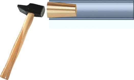
Friction fit tapered plugs (Picture below) shall only be used in services that meet all of the following conditions, unless an engineering evaluation is performed indicating the acceptability of these plugs in other services..
- Shell-side operating pressure 14 bar (200 psi) or less
- Shell-side operating temperature 205°C (400°F) or less
- Tube-to-tubesheet joints are expanded and not welded
Note.. Inspection of the expanded tube for tube thinning should be made to ensure that installation of the plug does not further damage the tube leading to seal failure between the plug and the tubes.
- Tapered plugs that are installed where tubes are not pierced can present a serious safety hazard. If the tube cannot be pierced, the tube should be pulled or other measures should be taken to ensure personnel protection, such as welding the plug to the tubesheet and draining all liquids from the tube being plugged.

Mechanical plugs
Mechanical plugs (Picture below) should be considered in situations where friction fit tapered plugs are not appropriate for the pressure and/or temperature of service or other mechanical/environmental conditions. These types of plugs have been used in services of up to 483 bar (7.000 psi) and 595°C (1.100°F). Mechanical plugs are typically installed
by a pneumatic or hydraulic system. Other styles of plugs may be considered for higher pressures.
Consideration shall also be given to the following..
- Tubes with internal surface severely corroded or cracked
- When the tube and the plug have dissimilar metallurgy
- Installation in severely corrosive service
- Condition of the mechanical joint of the tube to tubesheet in rolled tube situations

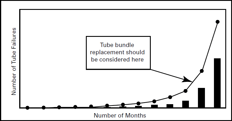
A plug map should be developed to record the number and location of tubes that have been plugged. Additionally, the number of tubes, cumulative number of tubes versus the duration, should be charted. When the sharp turn in tube failure numbers occurs, replacement of the tube bundle should be considered. See image below for example chart.
Sample Chart.. Number of Tube Failures by Month

Tracking of pressure loss due to tube pluggage should be considered as some exchanger types cannot function properly beyond certain tubeside pressure losses. Provisions for internal bypass should be considered if repair is not performed in order to prevent failure of pass partitions. Proper design of this bypass can be determined from industry references.
Reality and Practical Side
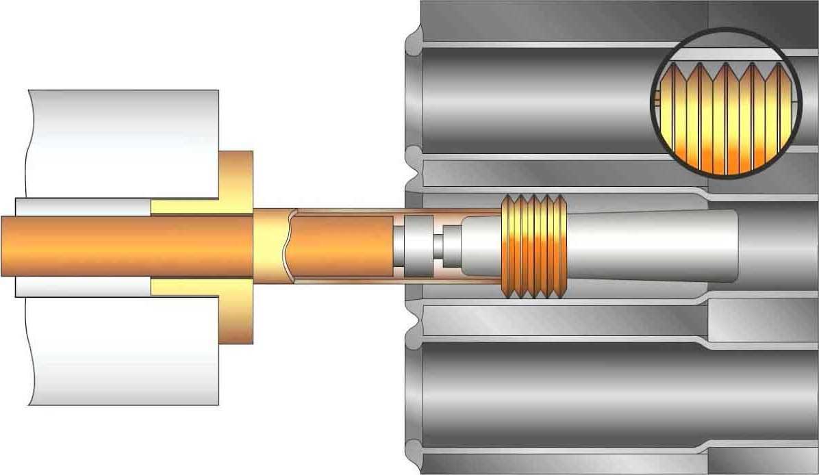
The Pop-A-Plug® image below system is a mechanical tube plug to seal leaking or degraded high-pressure heat exchanger tubes. The design ob-jective was to produce a fast and simple to in-stall mechanical tube plug with the same or bet-ter installed stability than a friction fit or welded plug.

The Pop-A-Plug® system eliminates the need for hammering or welding tube plugs. The system is long proven in fossil fuel and nuclear power generation stations. The Pop-A-Plug® heat exchanger tube plugging system is the only plug that features external and internal serrated rings designed to maintain a leak-tight seal un-der extreme thermal and pressure cycling.
The Pop-A-Plug® is installed using a controlled force, which protects against damage to tube sheet ligaments and the adjacent tube sheet joints.
Thus the life of your heat exchanger is ex-tended and costs are reduced when you need to re-tube.
Another advantage is the Pop-A-Plug® system takes only minutes to install.
The system is available in a wide array of materials and can be matched to the tube or tube sheet it is installed in. Matching the material eliminates differences in thermal expansion rates and ensures a perfect seal is maintained during temperature cycles experienced by the heat exchanger.
®Pop-A-Plug is a registered trademark of EST Group, Hatfield, PA, USA
- Pop-A-Plug® Heat Exchanger Tube Plugs
- Installation Training - Pop-A-Plug® P2 Heat Exchanger Tube Plugging System
- Pop-A-Plug® Tube Plug Installation, 6000 PsiG Test, and Removal
Reference(s) for the article..
ASME PCC-2
EST Group/Curtiss-Wright