 |
Piping & Instrumentation Diagram |
The Piping and Instrument Diagram (P&ID) provides a schematic representation of the piping, process control, and instrumentation which shows the functional relationships among the system components.
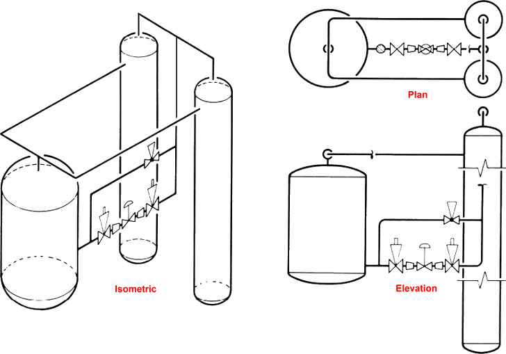
The P&ID also provides important information needed by the constructor and manufacturer to develop the other construction input documents (the isometric drawings or orthographic physical layout drawings).

The P&ID provides direct input to the field for the physical design and installation of field-run piping. For clarity, it is usual practice to use the same general layout of flow paths on the P&ID as used on the system flow diagram.
The P&ID ties together the system description, the system flow diagram, the electric control schematic, and the control logic diagram. It accomplishes this by showing all the piping, equipment, principal instruments, instrument loops, and control interlocks.
The P&ID contains a minimum amount of text in the form of notes (the system descriptions minimize the need for text on the P&ID). The first P&ID in the set for the job should contain a legend defining all symbols used; if certain symbols are defined elsewhere, it may be appropriate to only reference their Reference(s). The P&IDs are also used by the start-up organizations for preparing flushing, testing, and blowout procedures for the piping system and by the plant operators to operate the system. The correctness and completeness of the SD, SFD, and P&ID drawings are crucial to the success of the start-up program.
The P&ID should show the following
Instruments significant to the process piping including..
- Mechanical equipment
- All Valves associated with the process piping
- Process pipes
- Vents and drains
- Special fittings
- Sampling lines
- Permanent start-up and flushing lines
Specific information as applicable to job..
- Instrument designations
- Equipment names and numbers
- Pipeline identification
- Valve identification
All size transitions in line..
- Reducers and increasers, swages, etc
- Direction of flow
- Interfaces for class changes
- Seismic category
- Quality level
- Interconnection references
- Annunciation inputs
- Plant computer inputs
- Vendor and contractor interfaces
- Identification of components and subsystems by others
- Reference to a vendor drawing for details not shown
- Intended physical sequence of equipment.. including branch lines, reducers, etc.
Remark(s) of the Author...
The P&ID for a defined system should be limited to coverage of that system to the maximum practical extent. Other systems that interface with the subject system are shown in phantom if such portions are detailed elsewhere.
Whenever a line is broken off as a matter of drafting convenience, both the break and the continuation are labeled so that one can readily trace the line from both sides of the break. This applies whether the break and continuation are on the same sheet or on different sheets of the drawing.
Except for very simple P&ID, the drawing should have the horizontal and vertical borders marked to permit reference to any small area of the drawing, such as by "Continued at PG-12".
Care should be taken to ensure that these markings are within the sized field of the drawing so that they will always be reproduced with the drawing regardless of the process used.
Differences between P&ID’s and PFD’s
Piping and Instrumentation Diagrams (P&IDs) are often confused with Process Flow Diagrams (PFDs). P&IDs and PFDs generally use the same notation for teams. However, they serve different purposes and provide different information. The purpose of a PFD is to show exactly what a process does during operation, and a P&ID shows all controllers, valve types and materials used in construction.
A PFD shows the connectivity and relationships between the major equipment and units of a process. However, it also contains tabulated design values, such as normal, minimum and maximum operating conditions, that a P&ID does not contain. A PFD does not contain small piping systems or other small components that a P&ID normally contains.
The difference between P&IDs and PFDs is that P&IDs typically contain more information about piping, control and safety valves than process flow diagrams. P&IDs do not contain operational specifications that PFDs do, such as flows and flow compositions. It should be noted that the differences between PFDs and P&IDs can vary from plant to plant. Most plants have standards for creating and modifying these documents.
Both PFDs and P&IDs are controlled documents and must be maintained with a document control procedure.
Related Post(s)

A Process Flow Diagram (PFD) is a type of flowchart that illustrates the relationships between major components at an industrial plant...

Piping isometrics are generally produced from orthographic drawings and are important pieces of information to engineers...