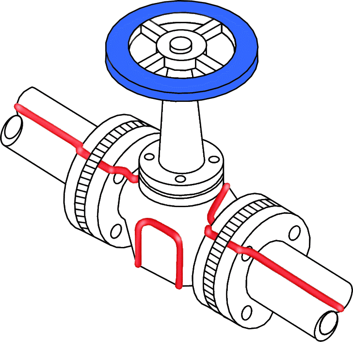
 |
Steam Tracing of Piping Systems |
Types of Heat Tracing Systems
Heat-tracing systems can be divided into two broad classes, electric and fluid. Fluid heat-tracing systems utilize heating media at elevated temperatures to transfer heat to a pipeline. The fluid is usually contained in a tube or a small pipe attached to the pipe being traced. If steam is the tracing fluid, the condensate is either returned to the boiler or dumped. If an organic heat-transfer fluid is employed, it is returned to a heat exchanger for reheating and recirculation. In general, heating of tracing fluids can be provided by waste heat from a process stream, burning of fossil fuels, steam, or electricity.
Electric heat-tracing systems convert electric power to heat and transfer it to the pipe and its contained fluid. The majority of commercial electric heat-tracing systems in use today are of the resistive type and take the form of cables placed on the pipe. When current flows through the resistive elements, heat is produced in proportion to the square of the current and the resistance of the elements to current flow. Other specialized electric tracing systems make use of impedance, induction, and skin conduction effects to generate and transfer heat.

Effective Steam Tracing
Steam tracing is the application of steam heat to piping and vessels for the purpose of maintaining desired process temperatures, freeze protection, viscosity control or to obtain a temperature control point within a fluid for its chemical interaction in a process.
Steam tracing is usually accomplished by running steam lines in direct contact with the piping or vessels to be heated. The entire assembly is then insulated to direct the heat into the process fluid. Many technical articles have been written concerning steam tracing along with their associated heat loss equations and graphs. Younger engineers, maintenance personnel, pipe fitters and others who steam trace do not always use effective methods for winterization and process temperature maintenance.
The need for steam tracing
Steam tracing is very simple in its principle of operation. When a product in a pipeline is at a higher temperature than the air surrounding it, heat will pass through the wall of the pipeline from the product to the surrounding air.
This heat loss will cause the temperature of the product to fall. Insulating the pipeline will significantly lower the rate at which heat is lost, but unfortunately, no insulation is 100% efficient.
Steam is a very efficient carrier of heat with a fixed relationship between its pressure and temperature. It can transport heat over long distances and gives up its heat at a constant temperature.
To make up the heat lost from the product pipeline, small bore steam pipes, or tracers, are attached to the product line. Heat from the steam passes into the product line and replaces the heat lost. The amount of heat transferred, and therefore the product temperature, can easily be controlled by simple self-acting control systems. The same type of control can also be used in winterization applications, only allowing steam into the tracing line when the ambient temperature falls below a predetermined level.
Remark(s) of the Author...
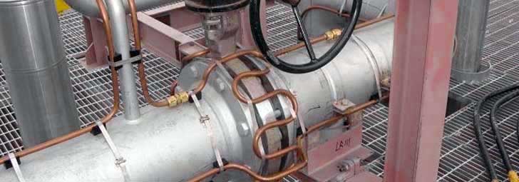
Copper Steam Heat Tracing with screwed couplings

The image above shows a pipeline traced with copper tubing. It looks good, but one thing is seriously wrong. If that pipeline is going to be insulated, the screwed couplings will also be insulated; and that is not the intention.
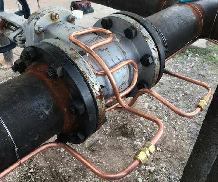
Screwed couplings always must be mounted outside the insulation, so that in case of leakage, it is visible which coupling is leaking; see image below. However, in the picture I am missing the insulation spacer blocks that should be placed between tracing and pipe and the valve.

I have experienced in the past that the insulation of hundreds of meters of pipeline had to be disassembled in order to find the leaking coupling. The costs were enormous, also in connection with scaffolding. So keep that in mind, and make sure that the steam tracing is installed correctly.
Types of steam heat tracing
- Jacketed - used in ultra-critical applications, usually where a product temperature has to be maintained at an elevated temperature all of the time. The use of a steam jacket also allows quick pre-heating of the pipeline.
- Critical - here, steam tracing is used to maintain the temperature of a product that will solidify or spoil should its temperature fall below a predetermined level.
- Non-critical - tracing is used to maintain the product viscosity at its optimum pumping level.
- Winterization - to ensure pipelines are not damaged due to freezing in adverse weather conditions.
- Instrument - small bore steam tracing pipes, normally 10 mm, used to protect flowmeters, control valves, sampling stations, impulse lines etc.
Jacketed Piping
Determining tracer requirements
To select the size and number of steam tracing lines required for a particular application, the rate of heat loss from the product pipeline under worst design conditions must be determined.
This rate of heat loss is dependant upon the difference between the product temperature and the ambient temperature. Other factors such as the thermal conductivity of the insulation, ambient wind speed and the emissivity of the insulation surface will affect this rate of loss.
Sizes and Lengths
The most common diameters of steam tracing are 3/8 in. (9.52 mm) and 1/2 in. (12.7 mm) OD copper or stainless steel tubing. Diameters of 5/8 in. (15.88 mm) and 3/4 in. (19.05 mm) OD tubing have been used; however, this entails greater expense. Tubing that is 3/8 in. is more easily plugged by sediment and/or debris, so it is less frequently used. Copper is preferred for its heat transfer characteristics, while stainless steel displays better resistance in corrosive environments.
Benefits of Steam Tracing Versus Other Methods
Though the benefits of each method can be debated, the table below shows the relative benefits and drawbacks of each system.
Due to the rising cost of energy, one of the key areas the plant needs to focus on is the tracer system's reliability and energy efficiency. The high usable heat content of steam offers many benefits over the use of thermal fluids for tracing and is significantly more efficient than electrical tracing.
As steam is primarily made of water, it has a low impact on the environment in the event of leakage to the atmosphere. It has been estimated that cleaning up a one-liter spill of glycol can cost up to $5,000.00. This cost includes the cleanup, reporting, and documentation required when a spill occurs on an industrial site. Steam is intrinsically safe, which makes it the practical choice for most industrial applications where ignition source must be minimized.
For these reasons, the use of steam tracing is still the preferred choice for temperature maintenance in most industrial and process applications.
Comparison of Steam Tracing and Other Methods
| Steam | Thermal Fluid | Elec. | |
| Cost of fluid | Low | Med | High |
| Cost of Comp. | Low | Med | High |
| Cost of Maint. | Low to high depending on maint. practices | Med | Low |
| Control of Temp. | High | Med | High |
| Temp. range | Med | High | Med |
| Length of Tracer | Med | Low | High |
| Intrinsically Safe | Yes | Yes | No |
| Energy Efficiency | High | Med | Low |
| Freeze-up Potential | Yes | No | No |
| Speed of Heat Up | High | Med | Low |
| Requires Pumping | No | Yes | No |
| Steam | Thermal Fluid | Elec. |
Remark(s) of the Author...
Conventional Steam Heat Tracing vs New Methods of Steam Heat Tracing
For conditions where the tracer could overheat lines containing acid, caustic, amine, phenolic water, or other chemicals, insulation spacer blocks shall be installed between tracer and pipe.
The old "spacer block" method was the best choice of the time to supply heat transfer rates below the rates that could be provided by convection tracing. Varying heat delivery requirements called for different spacing dimensions, and accuracy of design in such a system was difficult at best. Although the old tracing systems were not very sophisticated or efficient, they were made to work by the early pioneers in the refining, chemical, pulp and paper and other industries.
One was to suspend a bare tracer above the pipeline and attempt to maintain an air gap with spacer blocks. This system was problematic. The blocks were difficult to keep in place during assembly and thus were tedious and time consuming to install. They frequently slipped out of place in service because of the natural expansion and contraction of the tracer tube. This system was plagued with unpredictable heat transfer rates, hot spots, and high installation costs.
SafeTrace isolated steam tracing tubes from Thermon reduce steam consumption and burn risk
For over 40 years Thermon has been helping their heat tracing customers get more heat out of their steam tracing tubes, and now their heat efficiency is so good that many customers are demanding less heat.
To meet these demands, Thermon have created the SafeTrace series of isolated steam tracing tubes specifically designed to winterise pipes while reducing burn risks and decreasing steam consumption compared to conventional bare tube steam tracers.
Designed to provide the accurate and predictable heat transfer properties required to maintain temperature sensitive or corrosive products, SafeTrace steam tracing tubes permit winterisation of any sized pipe and eliminate the hot and cold spots associated with bare metal tracers and spacer blocks.

SafeTrace steam tracing tubes comply with ASTM Std C-1055 for skin exposure temperatures of less than 58°C when in contact with a hot surface for five seconds, and a safety yellow jacket alerts plant personnel to inherently dangerous materials, such as steam, as per ASME/ANSI A13.1-1996.
Easily installed without the need for channels, spacer blocks or metallic attachment bands, SafeTrace steam tracing tubes are simply attached to the pipeworks or vessel with temperature rated adhesive tape. This reduces installation costs by requiring 1/3 less labor than spacer blocks and eliminates the need for transition lines and fittings. Furthermore, fewer fittings cuts maintenance and repairs.
References
- www.interstates.com
- www.spiraxsarco.com
- www.thermon.com
- Nayyar, M., ed. Piping Handbook,
Heattracing of piping systems