Weld End Preparation at Unequal Wall Thicknesses
Acceptable Design in Piping components
In most piping systems there are components such as valves, castings, heavier header sections, and equipment nozzles which are welded to the pipe.
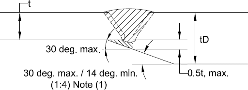
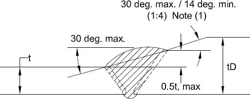
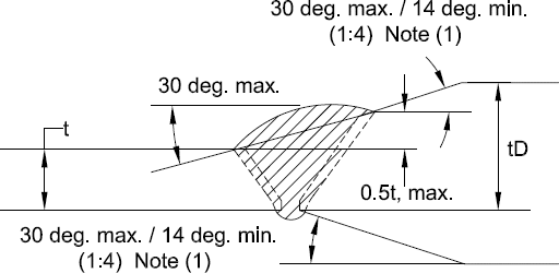
In such instances the heavier sections are machined to match the lighter pipe wall and the excess thickness tapered both internally and externally to form a transition zone.
Limits imposed by the various codes for this transition zone are fairly uniform.
The external surface of the heavier component is tapered at an angle of 30° maximum for a minimum length equal to 1.1/2 times the pipe minimum wall thickness and then at 45° for a minimum of 1.1/2 times the pipe minimum wall.
Internally, either a straight bore followed by a 30° slope or a taper bore at a maximum slope of 1 to 4 for a minimum distance of 2 times the pipe minimum wall are required.
The surface of the weld can also be tapered to accommodate differing thickness. This taper should not exceed 30°. It may be necessary to deposit weld metal to assure that these limits are not violated.
Below some tables with acceptable design for unequal wall thicknesses according to ASME B31.8
Internal Offset
A

Internal Offset
B

Internal Offset
C

Internal Offset
D

External Offset
E

External Offset
F

Combination Offset
G

Note (1)..
No minimum when materials joined have equal specified minimum yield strengths.