 |
Heat Exchanger Shell Assembly |
The shell is constructed either from pipe up to 24" or rolled and welded plate metal. For reasons of economy, low carbon steel is in common use, but other materials suitable for extreme temperature or corrosion resistance are often specified.
Using commonly available shell pipe to 24" in diameter results in reduced cost and ease of manufacturing, partly because they are generally more perfectly round than rolled and welded shells.
Roundness and consistent shell ID is neccessary to minimize the space between the baffle outside edge and the shell as excessive space allows fluid bypass and reduced performance. Roundness can be increased by expanding the shell around a mandrell or double rolling after welding the longitudnal seam. In extreme cases the shell can be cast and then bored to the correct ID.
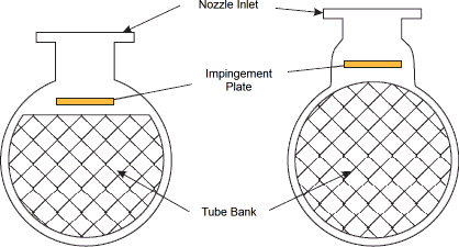
In applications where the fluid velocitiy for the nozzle diameter is high, an impingement plate is specified to distribute the fluid evenly to the tubes and prevent fluid enduced erosion, cavitation and vibration.
An impingement plate can be installed inside the shell, which prevents installing a full tube bundle, resulting in less available surface. It can alternately be installed in a domed area above the shell. The domed area can either be reducing coupling or a fabricated dome. This style allows a full tube count and therefore maximizes the utilization of shell space.

End channels and Bonnets
End channels or Bonnets are typically fabricated or cast and control the flow of the tubeside fluid in the tube circuit. They are attached to the tube sheets by bolting with a gasket between the two metal surfaces. In some cases, effective sealing can be obtained by installing an O-ring in a machined groove in the tube sheet.
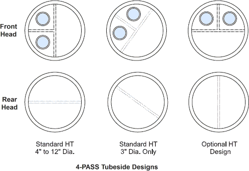
The head may have pass ribs that dictate if the tube fluid makes one or more passes through the tube bundle sections. Front and rear head pass ribs and gaskets are matched to provide effective fluid velocities by forcing the flow through various numbers of tubes at a time.
Generally, passes are designed to provide roughly equal tube-number access and to assure even fluid velocity and pressure drop throughout the bundle. Even fluid velocities also affect the film coefficients and Heat Transfer rate so that accurate prediction of performance can be readily made. Designs for up to six tube passes are common. Pass ribs for cast heads are intregrally cast and then machined flat. Pass ribs for fabricated heads are welded into place.
The tube sheets and tube layout in multi-pass Heat Exchangers must have provision for the pass ribs. This requires either removing tubes to allow a low cost straight pass rib, or machining the pass rib with curves around the tubes, which is more costly to manufacture. Where a full bundle tube count is required to satisfy the thermal requirements, this machined pass rib approach may prevent having to consider the next larger shell diameter. Cast head materials are typically used in smaller diameters to around 14" and are made from iron, ductile iron, steel, bronze or stainless steel. They typically have pipethread connections. Cast heads and tube side piping must be removed to service tubes.

Fabricated heads can be made in a wide variety of configurations. They can have metal cover designs that allow servicing the tubes without disturbing the shell or tube piping. Heads can have axially or tangentially oriented nozzles, which are typically ASME flanges.
Baffles
Baffles serve two important functions. They support the tubes during assembly and operation and help prevent vibration from flow induced eddies and direct the shell side fluid back and forth across the tube bundle to provide effective velocity and Heat Transfer rates.
The diameter of the baffle must be slightly less than the shell inside diameter to allow assembly, but must be close enough to avoid the substantial performance penalty caused by fluid bypass around the baffles. Shell roundness is important to acheive effective sealing against excessive bypass.
Baffles can be made from a variety of materials compatible with the shell side fluid. They can be punched or machined. Some baffles are made by a punch which provides a lip around the tube hole to provide more surface against the tube and eliminate tube wall cutting from the baffleedge.
The tube holes must be precise enough to allow easy assembly and field tube replacement, yet minimize the chance of fluid flowing between the tube wall and baffle hole, resulting in reduced thermal performance and increased potential for tube wall cutting from vibration.
Baffles do not extend edge to edge, but have a cut that allows shell side fluid to flow to the next baffled chamber. For most liquid applications, the cuts areas represent 20-25% of the shell diameter. For gases, where a lower pressure drop is desirable, baffle cuts of 40-45% is common.
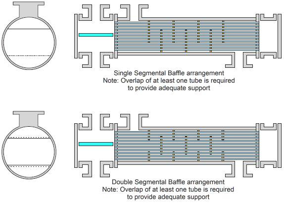
Baffles must overlap at least one tube row in order to provide adequate tube support. They are spaced throughout the tube bundle somewhat evenly to provide even fluid velocity and pressure drop at each baffled tube section.

Single-segmental baffles force the fluid or gas across the entire tube count, where is changes direction as dictated by the baffle cut and spacing. This can result in excessive pressure loss in high velocity gases.
In order to effect Heat Transfer, yet reduce the pressure drop, double-segmental baffles can be used. This approach retains the structural effectiveness of the tube bundle, yet allows the gas to flow between alternating sections of tube in a straighter overall direction, thereby reducing the effect of numerous changes of direction.
This approach takes full advantage of the available tube surface but a reduction in performance can be expected due to a reduced Heat Transfer rate. Because pressure drop varies with velocity, cutting the velocity in half by using doublesegmental baffles results in roughly1/4 of the pressure drop as seen in a single-segmental baffle space over the same tube surface.
Other Pages about Heat Exchangers