Dimensions 6B Flanges API 6A 3000 PSI Working Pressure
OTHER PRESSURE CLASSES
3000 PSI
|
Pressure Ratings Flanges for Wellhead and Christmas Tree Equipment Weld Neck, Integral, Blinds, Targets and Test Blinds |
|||
| Max Working Pressure |
2000 PSI |
3000 PSI |
5000 PSI |
| Test Pressure | 3000 PSI | 4500 PSI | 7500 PSI |
| Product Spec Levels |
1, 2, 3 and 4 | 1, 2, 3 and 4 | 1, 2, 3 and 4 |
| API Temp Rating |
K (-60 ° C) to Y (+345 ° C) |
K (-60 ° C) to Y (+345 ° C) |
K (-60 ° C) to Y (+345 ° C) |
|
Integral, Blind, Target Blind and Test Flanges |
|||
| Min. Yield | 60 000 PSI | 60 000 PSI | 60 000 PSI |
| Min. Tensile | 85 000 PSI | 85 000 PSI | 85 000 PSI |
| Material | API 60K | API 60K | API 60K |
|
Weld Neck Flanges |
|||
| Min. Yield | 45 000 PSI | 45 000 PSI | 45 000 PSI |
| Min. Tensile | 70 000 PSI | 70 000 PSI | 70 000 PSI |
| Material | API 45K | API 45K | API 45K |
|
Pressure Ratings Flanges for Wellhead and Christmas Tree Equipment Weld Neck, Integral, Blinds, Targets and Test Blinds |
|||
| Max Working Pressure |
10 000 PSI |
15 000 PSI |
20 000 PSI |
| Test Pressure | 15 000 PSI | 22 500 PSI | 30 000 PSI |
| Product Spec Levels |
1, 2, 3 and 4 | 1, 2, 3 and 4 | 1, 2, 3 and 4 |
| API Temp Rating |
K (-60 ° C) to Y (+345 ° C) |
K (-60 ° C) to Y (+345 ° C) |
K (-60 ° C) to Y (+345 ° C) |
|
Integral, Blind, Target Blind and Test Flanges |
|||
| Min. Yield | 60 000 PSI | 75 000 PSI | 75 000 PSI |
| Min. Tensile | 85 000 PSI | 95 000 PSI | 95 000 PSI |
| Material | API 60K | API 75K | API 75K |
|
Weld Neck Flanges |
|||
| Min. Yield | 60 000 PSI | 75 000 PSI | 75 000 PSI |
| Min. Tensile | 85 000 PSI | 95 000 PSI | 95 000 PSI |
| Material | API 60K | API 75K | API 75K |
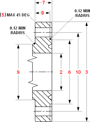
Flange Section Integral

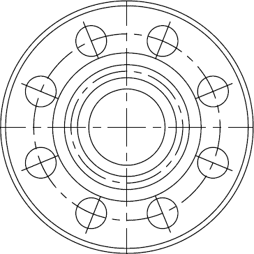
Top View

| 1. Nominal Size and Bore of Flange |
2. Max Bore | 3. Outside Dia Flange |
4. Tolerance (3) |
| 5. Max Chamfer | 6. Dia Raised Face |
7. Total Thk Flange |
8. Basic Thk Flange |
| 9. Dia Hub | 10. Dia Bolt Circle |
11. Number of Bolt Holes |
12. Dia of Bolts |
| 13. Dia Bolt Holes |
14. Bolt Hole Tolerance (Minimum -0.02) |
15. Length Stud Bolts |
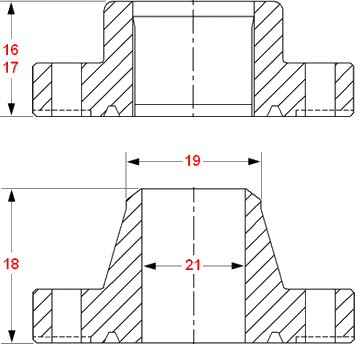
16. Hub Length Threaded Line-Pipe Flange |
| 17. Hub Length Threaded Casing Flange |
18. Hub Length Welding Neck Line-Pipe Flange ±0.06 |
19. Neck Dia Welding Neck Line-Pipe Flange |
20. Tolerance (19) |
| 22. Ring Number R or RX |
| 1 | 2 | 3 | 4 | 5 | 6 |
| 2.1/16 | 2.09 | 8.5 | ± 0.06 | 0.12 | 4.88 |
| 2.9/16 | 2.59 | 9.62 | ± 0.06 | 0.12 | 5.38 |
| 3.1/8 | 3.22 | 9.5 | ± 0.06 | 0.12 | 6.12 |
| 4.1/16 | 4.28 | 11.5 | ± 0.06 | 0.12 | 7.12 |
| 5.1/8 | 5.16 | 13.75 | ± 0.06 | 0.12 | 8.5 |
| 7.1/16 | 7.16 | 15 | ± 0.12 | 0.25 | 9.5 |
| 9 | 9.03 | 18.5 | ± 0.12 | 0.25 | 12.12 |
| 11 | 11.03 | 21.5 | ± 0.12 | 0.25 | 14.25 |
| 13.5/8 | 13.66 | 24 | ± 0.12 | 0.25 | 16.5 |
| 16.3/4 | 16.78 | 27.75 | ± 0.12 | 0.25 | 20.62 |
| 20.3/4 | 20.78 | 33.75 | ± 0.12 | 0.25 | 25.5 |
| 1 | 7 | 8 | 9 | 10 | 11 |
| 2.1/16 | 1.81 | 1.5 | 4.12 | 6.5 | 8 |
| 2.9/16 | 1.94 | 1.62 | 4.88 | 7.5 | 8 |
| 3.1/8 | 1.81 | 1.5 | 5 | 7.5 | 8 |
| 4.1/16 | 2.06 | 1.75 | 6.25 | 9.25 | 8 |
| 5.1/8 | 2.31 | 2 | 7.5 | 11 | 8 |
| 7.1/16 | 2.5 | 2.19 | 9.25 | 12.5 | 12 |
| 9 | 2.81 | 2.5 | 11.75 | 15.5 | 12 |
| 11 | 3.06 | 2.75 | 14.5 | 18.5 | 16 |
| 13.5/8 | 3.44 | 3.12 | 16.5 | 21 | 20 |
| 16.3/4 | 3.94 | 3.5 | 20 | 24.25 | 20 |
| 20.3/4 | 4.75 | 4.25 | 24.5 | 29.5 | 20 |
| 1 | 12 | 13 | 14 | 15 | 16 |
| 2.1/16 | 7/8 | 1 | +0.06 | 6 | 2.56 |
| 2.9/16 | 1 | 1.12 | +0.06 | 6.5 | 2.81 |
| 3.1/8 | 7/8 | 1 | +0.06 | 6 | 2.44 |
| 4.1/16 | 1.1/8 | 1.25 | +0.06 | 7 | 3.06 |
| 5.1/8 | 1.1/4 | 1.38 | +0.06 | 7.75 | 3.44 |
| 7.1/16 | 1.1/8 | 1.25 | +0.06 | 8 | 3.69 |
| 9 | 1.3/8 | 1.5 | +0.06 | 9 | 4.31 |
| 11 | 1.3/8 | 1.5 | +0.06 | 9.5 | 4.56 |
| 13.5/8 | 1.3/8 | 1.5 | +0.06 | 10.25 | 4.94 |
| 16.3/4 | 1.5/8 | 1.75 | +0.09 | 11.75 | 5.06 |
| 20.3/4 | 2 | 2.12 | +0.09 | 14.5 | 6.75 |
| 1 | 17 | 18 | 19 | 20 | 21 | 22 |
| 2.1/16 | 4.31 | 2.38 | +0.09 -0.03 |
1.97 | 24 | |
| 2.9/16 | 4.44 | 2.88 | +0.09 -0.03 |
2.35 | 27 | |
| 3.1/8 | 4.31 | 3.5 | +0.09 -0.03 |
2.93 | 31 | |
| 4.1/16 | 3.5 | 4.81 | 4.5 | +0.09 -0.03 |
3.86 | 37 |
| 5.1/8 | 4 | 5.31 | 5.56 | +0.09 -0.08 |
4.84 | 41 |
| 7.1/16 | 4.5 | 5.81 | 6.63 | +0.16 -0.03 |
5.79 | 45 |
| 9 | 5 | 6.69 | 8.63 | +0.16 -0.03 |
7.47 | 49 |
| 11 | 5.25 | 7.56 | 10.75 | +0.16 -0.03 |
9.34 | 53 |
| 13.5/8 | 4.94 | 57 | ||||
| 16.3/4 | 5.69 | 66 | ||||
| 20.3/4 | 6.75 | 74 |

Note..All dimensions are in inches