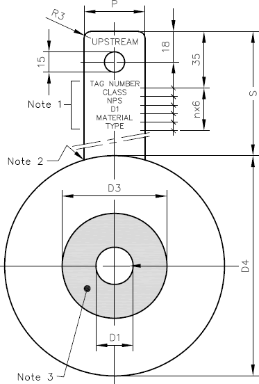
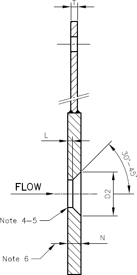
Dims. Restriction Orifice Plates
Dimensions of Restriction Orifice Plates for ASME B16.5 RF Flanges


| NPS | DIA D3 |
L | N | P | T |
| 1/2 | 13 | 0.24 | 1.5 | 30 | 1.5 |
| 3/4 | 19 | 0.34 | 1.5 | 30 | 1.5 |
| 1 | 25 | 0.42 | 2 | 30 | 2 |
| 1.1/2 | 40 | 0.64 | 3 | 30 | 3 |
| 2 | 51 | 1 | 6 | 30 | 3 |
| 3 | 76 | 1.5 | 8 | 40 | 3 |
| 4 | 102 | 1.5 | 10 | 40 | 5 |
| 6 | 152 | 1.5 | 15 | 40 | 5 |
| 8 | 202 | 3.5 | 15 | 40 | 7 |
| 10 | 253 | 3.5 | 19 | 45 | 7 |
| 12 | 302 | 3.5 | 20 | 45 | 10 |
| 14 | 341 | 6 | 20 | 45 | 10 |
| 16 | 392 | 6 | 21 | 50 | 11 |
| 18 | 443 | 8 | 23 | 50 | 13 |
| 20 | 494 | 8 | 25 | 50 | 16 |
| 24 | 595 | 10 | 29 | 60 | 18 |
| NPS | ASME B16.5 Flange Class | |||||
| 150 | 300 | 600 | 900 | 1500 | 2500 | |
| S | ||||||
| 1/2 | 110 | 110 | 110 | 115 | 115 | 120 |
| 3/4 | 110 | 110 | 110 | 115 | 115 | 120 |
| 1 | 110 | 115 | 115 | 120 | 120 | 125 |
| 1.1/2 | 110 | 120 | 120 | 125 | 125 | 130 |
| 2 | 110 | 115 | 115 | 125 | 125 | 130 |
| 3 | 115 | 120 | 120 | 125 | 135 | 140 |
| 4 | 115 | 125 | 125 | 130 | 140 | 150 |
| 6 | 115 | 120 | 130 | 135 | 145 | 170 |
| 8 | 120 | 125 | 135 | 145 | 155 | 170 |
| 10 | 120 | 130 | 145 | 145 | 165 | 190 |
| 12 | 125 | 135 | 140 | 145 | 165 | 195 |
| 14 | 130 | 140 | 145 | 150 | 175 | |
| 16 | 130 | 145 | 150 | 155 | 180 | |
| 18 | 130 | 145 | 155 | 160 | 195 | |
| 20 | 135 | 150 | 155 | 165 | 205 | |
| 24 | 135 | 160 | 165 | 190 | 2205 | |
| NPS | ASME B16.5 Flange Class | |||||
| 150 | 300 | 600 | 900 | 1500 | 2500 | |
| DIA D4 |
||||||
| 1/2 | 48 | 54 | 54 | 64 | 64 | 70 |
| 3/4 | 57 | 67 | 67 | 70 | 70 | 77 |
| 1 | 67 | 73 | 73 | 80 | 80 | 86 |
| 1.1/2 | 86 | 96 | 96 | 99 | 99 | 118 |
| 2 | 105 | 111 | 111 | 143 | 143 | 146 |
| 3 | 137 | 149 | 149 | 168 | 175 | 197 |
| 4 | 175 | 181 | 194 | 206 | 209 | 235 |
| 6 | 222 | 250 | 266 | 289 | 282 | 317 |
| 8 | 279 | 307 | 320 | 358 | 352 | 387 |
| 10 | 339 | 361 | 399 | 434 | 434 | 475 |
| 12 | 409 | 422 | 456 | 497 | 520 | 549 |
| 14 | 450 | 485 | 491 | 519 | 577 | |
| 16 | 513 | 539 | 564 | 573 | 640 | |
| 18 | 548 | 596 | 611 | 637 | 703 | |
| 20 | 605 | 653 | 681 | 697 | 754 | |
| 24 | 716 | 773 | 789 | 836 | 899 | |
TOLERANCES
D1
&
D2 = ± 1%
D3 = ± 1 mm
D4 = 0/-0.4 mm
L = ± 0.1 mm
N = see note 6
P = ± 0.1 mm
S = ± 0.1 mm
T = see note 2
Notes..
- Marking
The Upstream side of the orifice tab shall be stamped at the indicated locations with..
- the word UPSTREAM
- the Tag Number
- the ASME flange class, followed by RF
- the nominal pipe size (NPS)
- the measured orifice D1 (in mm)
- the material of the orifice plate
- the type of orifice plate (Square, Restriction etc.)
Letter height approx. 4 mm
- Welding of tab
Tab may be integral with orifice plate up to and including 7 mm plate thickness. In other cases full penetration joint to be applied.
- Finish of plate
The upstream and downstream faces of the orifice plate to a diameter equal to D3 shall have a surface roughness Ra ≤ 0.8 µm ASME B46.1. The remaining annular part (between D4 & D3) of upstream and downstream faces shall have a surface roughness Ra between 3.2 and 3.6 µm ASME B46.1. This finish shall be obtained by machining with a round nosed cutting tool having a 0.8 mm radius at a feed rate between 0.35 and 0.45 mm per revolution.
- Concentricity
The centre of the orifice shall not differ from the centre of the plate by more than 0.1 mm for ≤ NPS 8 and 0.2 mm for > NPS 8.
- Finish of throat
The throat and outlet cone shall have a surface roughness Ra ≤ 0.4 µm ASME B46.1. All edges shall be sharp and free from burrs, so that when viewed with the naked eye no light is reflected by the corners.
- Plate thickness
The difference between any two measurements of plate thickness, for annular part D1-D3, shall not differ by more than 0.001 DN in mm. The plate shall not depart from flatness along any diameter by more than 0.01 D3. Tolerance for N shall be..N ≤ 6 mm +0.1/-0.25 mm N > 6 mm +0/-1.5 mm. Thickness for annular part D3-D4, may be slightly less, max 0.05 mm, due to surface finishing difference between D1-D3 & D3-D4. (see note 3)
General notes..
- Dimensions are in millimeters unless otherwise indicated.
- Allowable pressure difference 20 bar for temperatures up to 400 °C and D1/D3 ≥ 0.1. The thickness of the plate needs to be verified for strength in case the pressure difference is higher than 20 bar and/or the temperature is beyond 400 °C. Based on the outcome of the calculation the thickness of the plate needs to be adjusted.
- DIA D1 & DIA D2 - to be specified by purchaser.
- Material to be specified by purchaser.