What are Drip Legs in Steam Piping?
Drip Legs are vertical pipe pockets along the main steam line where condensate is collected for drainage from the system. The design, construction and location of Drip Legs are all important aspects to consider for reliable operation of the steam utility and efficient operation of the heat transfer processes and equipment.
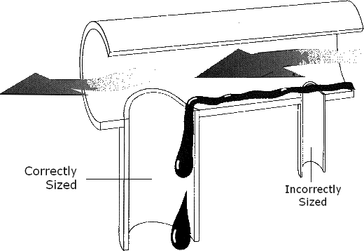
Some people think that creating a Drip Leg is simply a matter of connecting piping or equipment to a steam trap of the correct size. However, an analysis of the varying conditions in a steam system reveals that the location and sizing of Drip Legs is much more complex than it first appears.
How Drip Legs Work
Drip legs use the force of gravity to collect condensate. Since water is heavier than steam, it flows to the lowest point in the system. In well-designed systems, this is where you will find the Drip Legs.
There are two components that make up a Drip Leg. First, you have a section of pipe that drops below the surrounding pipe. This allows condensate to be collected from the system. Second, you have a trap that allows this condensate to exit the system without allowing steam to escape.
Drip Leg Design
According to Armstrong International..
Startup Conditions
During startup, high condensate loads are created as steam condenses after encountering cool pipes and equipment. At the same time, the high condensation rate leaves little steam pressure in the pipes. If the system is properly designed, gravity will draw condensate into the Drip Leg. During assisted startup, a valve is manually opened to drain and gravity alone is sufficient to drain condensate.
However, in automatic start-up, there may not be sufficient pressure differential to provide flow through a steam trap opening. In these cases, the Drip Leg must be long enough to provide the necessary static head to push condensate through the steam trap.
Typical steam trap-draining

Values for M, D, and H are provided in the table below.
Sizing of Steam Main and Branch Line Drip Leg
Dimensions are in inches
| M | D | H | |
| Drip Leg Length |
|||
| Steam Main Size |
Drip Leg Dia. |
Supervised Warm-Up |
Automatic Warm-Up |
| 1/2 | 1/2 | 10 | 28 |
| 3/4 | 3/4 | 10 | 28 |
| 1 | 1 | 10 | 28 |
| 2 | 2 | 10 | 28 |
| 3 | 3 | 10 | 28 |
| 4 | 4 | 10 | 28 |
| 6 | 4 | 10 | 28 |
| 8 | 4 | 12 | 28 |
| 10 | 6 | 15 | 28 |
| 12 | 6 | 18 | 28 |
| 14 | 8 | 21 | 28 |
| 16 | 8 | 24 | 28 |
| 18 | 10 | 27 | 28 |
| 20 | 10 | 30 | 30 |
| 24 | 12 | 36 | 36 |
| Dimensions in the table above are in inches | |||
Drip Leg Locations
Drip legs can be placed anywhere condensate can accumulate in the system, but they have a few common locations. This includes a location just before the steam reaches its destination. Placing a Drip Leg in this location ensures that all of the condensate is drained and pure steam reaches the process.
Drip Legs can also be found at the end of a steam line. A good rule of thumb is that Drip Legs should be located at approximately 90 meters (300 ft) intervals and no more than 152 meters (500 ft) intervals.
When there is a difference in elevation in the steam line that is going up, a Drip Leg should be used. This is to catch any condensate that would collect at the lowest point due to the vertical lines.
Reduce condensation
Making sure all lines in the system are insulated can reduce the amount of condensation that is produced. Next, make sure there is no deflection in the steam supply line. Deflection creates low points where condensate can collect. This can lead to water hammer, corrosion, and a decrease in the efficiency of the system. Properly supporting steam lines can eliminate this problem.
To summarize, any point in a steam system where pressure, velocity or heat is lost is a place where a Drip Leg can be placed.